J-K Flip-Flop

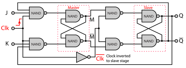
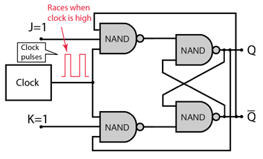
The J-K flip-flop is the most versatile of the basic flip-flops. It has the input- following character of the clocked D flip-flop but has two inputs,traditionally labeled J and K. If J and K are different then the output Q takes the value of J at the next clock edge. The inputs are labeled J and K in honor of the inventor of the device, Jack Kilby.

Examine StructureApplications

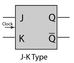
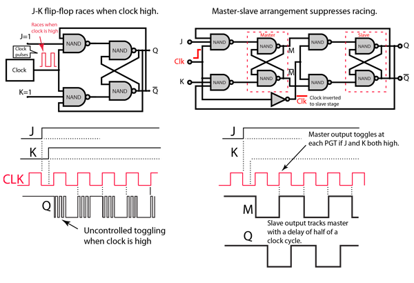
If J and K are both low then no change occurs. If J and K are both high at the clock edge then the output will toggle from one state to the other. It can perform the functions of the set/reset flip-flop and has the advantage that there are no ambiguous states. It can also act as a T flip-flop to accomplish toggling action if J and K are tied together. This toggle application finds extensive use in binary counters.

Flip-Flops
Index

Electronics concepts

Digital circuits

Sequential Operations

J-K Flip-Flop Applications
 
HyperPhysics*****Electricity and magnetismR Nave
Go Back


J-K Flip-Flop Structure

A simplified version of the versatile J-K flip-flop. Note that the outputs feed back to the enabling NAND gates. This is what gives the toggling action when J=K=1.

While this implementation of the J-K flip-flop with four NAND gates works in principle, there are problems that arise with the timing. The timing pulse must be very short because a change in Q before the clock pulse goes off can drive the circuit into an oscillation called "racing". Modern ICs are so fast that this simple version of the J-K flip-flop is not practical (we put one together in the lab with an available 4-NAND chip and it was very unstable against racing).

The next step in making use of the versatile J-K flip-flop is to use four additional NAND gates to create the Master-Slave JK Flip Flop which has two gated SR flip flops used as latches in a way that suppresses the "racing".
Switching Example
Flip-Flops

Index

Electronics concepts

Digital circuits

Electronics Tutorials

allaboutcircuits
 
HyperPhysics*****Electricity and magnetismR Nave
Go Back


Switching Example: Master-Slave J-K Flip-Flop

The positive going transition (PGT) of the clock enables the switching of the output Q. The "enable" condition does not persist through the entire positive phase of the clock. The J & K inputs alone cannot cause a transition, but their values at the time of the PGT determine the output according to the truth table. This is an application of the versatile J-K flip-flop. Since this 4-NAND version of the J-K flip-flop is subject to the "racing" problem, the Master-Slave JK Flip Flop was developed to provide a more stable circuit with the same function.

The Master-Slave JK Flip Flop has two gated SR flip flops used as latches in a way that suppresses the "racing" or "race around" behavior. Another way to look at this circuit is as two J-K flip-flops tied together with the second driven by an inverted clock signal.

When the clock makes a positive transition the master section is triggered but the slave section is not because its clock is inverted. At a half cycle of the clock, on the downward transition, the inverted clock has a positive transition and triggers the slave section. The final output Q then tracks the output of the master section M after a half cycle of the clock.

Flip-Flops
Index

Electronics concepts

Digital circuits

Reference
Tocci
Digital Systems, p170

Digital circuits

Electronics Tutorials

allaboutcircuits
 
HyperPhysics*****Electricity and magnetismR Nave
Go Back


J-K Flip-Flop Data Transfer

In synchronous data transfer between two J-K flip-flops, a transfer signal on the clock input causes transfer from cell A to cell B. The transfer signal could be applied to several such cells in series to create a shift register.

In asynchronous data transfer, a transfer pulse may be applied at any time to force the data onto the asychronous set and clear inputs, storing the data regardless of what is happening on the other inputs.

Flip-Flops
Index

Electronics concepts

Digital circuits

Data Transfer

J-K Flip-Flop Applications

Reference
Tocci
Digital Systems, Sec 5-9, 5-17
 
HyperPhysics*****Electricity and magnetismR Nave
Go Back


J-K Flip-Flop Instability or "Racing"

A simplified version of the versatile J-K flip-flop. Note that the outputs feed back to the enabling NAND gates. This is what gives the toggling action when J=K=1. The toggling might be a desired behavior, but generally you would like for the times of toggling to be controlled by the clock pulses as enablers so that you could control and predict the output.

For this version of the J-K flip-flop under the input conditions J=K=1 the toggling would be enabled anytime the clock has value 1, and the toggling rate would be determined by the propagation delay around the circuit. The value of the output at any time would not be predictable from the clock state. This is called "racing" or the "race-around condition". This uncontrolled toggling can be suppressed by using the master-slave arrangement where the transmission of the J value to the output is delayed by half a clock cycle and not immediately fed back to the input side.

Switching Example
Flip-Flops
Index

Electronics concepts

Digital circuits

Data Transfer

J-K Flip-Flop Applications

References
Tocci
Digital Systems, Sec 5-9, 5-17

ECE Turorials/
 
HyperPhysics*****Electricity and magnetismR Nave
Go Back