Atomic Spectra
Interference and Diffraction
Interference and diffraction are traveling wave phenomena. When light is forced to go through a narrow slit or pinhole or when it passes a sharp-edged obstruction, it shows its wave nature. For example, when the shadow of a razor blade is examined under high magnification it is found to be a series of closely-spaced bright and dark bands. The series of bands is called a diffraction pattern. Diffraction and interference in waves are the result of reinforcement or cancelation of waves when different waves are at the same point in space at the same time. If the diffraction pattern of the razor's edge is viewed in blue light and then in red light, it is found that the bright and dark bands are closer together in the blue light because its wavelength is shorter. This is one way to confirm the basic theories about the wave nature of light.
 |
|
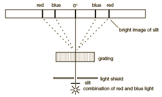
Diffraction through a series of closely spaced slits (called a grating) serves a useful purpose for the examination of the different wavelengths of light. Diffraction of a narrow beam of light of a single wavelength by a grating will produce a bright beam straight ahead and a series of beams to either side at angles where the light waves from adjacent slits reinforce each other. The first bright image to either side occurs when the difference in the pathlength of the light from adjacent slits of the grating is one wavelength, and it is called the "first order" diffraction maximum. When the pathlength difference is two wavelengths, another bright image occurs (the second order diffraction maximum). If light of a longer wavelength is used, the maxima are at larger angles. When light of multiple wavelengths is used, the different wavelengths(different colors) are separated. The separation of the colors is much larger than that obtained with a prism, so a diffraction grating can be thought of as a "super prism".
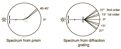
The gratings to be used in this experiment are transmission gratings which are made by ruling a large number of equally spaced parallel lines on a piece of glass, only a few wavelengths apart. The transparent positions between the lines act as narrow slits. The sketch below compares the spectra produced by a prism and a grating. The experiment involves a careful examination of the spectra (collection of separated wavelengths of light) for several light sources. In each case you are to examine the first order spectrun to the right of the zero angle. The relationship between the wavelength of the light and the angle of diffraction is
where n is the order number, q is the angle of diffraction, and d is the distance between grating lines. For these gratings, there are 600 lines/mm which corresponds to a grating spacing of d = 1670 nanometers. The sine of the angles you measure ( sin q )
Procedure
1. Place the diffraction grating in the mount at the center of the round metal diffractometer table and align it perpendicular to the path of the light.
2. Place the helium spectral tube in the holder and adjust its position for maximum intensity when viewed through the slit from the front.
a. View the slit through the telescope. Note the angle reading when the cross hairs are on the slit. If it is not zero, consult the lab supervisor.
b. Locate the first order green line to the right. It should be at about the 18° position. Record its angle.
c. Locate the same first order line to the left. Record its angle from zero (that is, 360° - qleft).
d. Find the average of the results of parts b. and c. Place the telescope at the average angle to the right.
e. Carefully rotate the grating until the same green line is at the crosshair. This places the grating perpendicular to the light beam. DO NOT MOVE THE GRATING FOR THE REMAINDER OF THE LAB.
3. View the first order (right) spectrum of helium and record the angle of each bright line with a line on one of the angle graphs provided. Indicate the color of the line.
4. Repeat (3.) with the hydrogen(H) and mercury (Hg) tubes. Observe the neon(Ne) tube, but you are not required to plot those lines.
5. View the incandescent source. Recond on a graph the two angles of the extremes of the spectrum. Next, scan the spectrum and record the angles at which you find "pure" red, orange, yellow, green, blue, and violet. Use these measurements to indicate the corresponding color bands on your plot.
QUESTIONS
1. Using the formula for wavelength, determine the wavelength for the two extremes found in part 5.
2. What is the approximate wavelength of red light?
3. What is the minimum wavelength you eye detected in the incandescent light.
4. If the wavelength of light is 500 nm, what color is it?
Equipment: Atomic Spectra
- Spectrometer table with grating holder and telescopic viewer
- Black light masks for spectrometers
- Spectra power supply/holder
- Spectra tubes for hydrogen, helium, mercury, neon
- Lamps
- Gratings
- Lab jack for positioning spectra tube apparatus
Experimental tips:
Put spectral tube close to slit to maximize intensity and minimize glare
Focus crosshairs while you are at zero, looking directly at slit.