AM Transmission
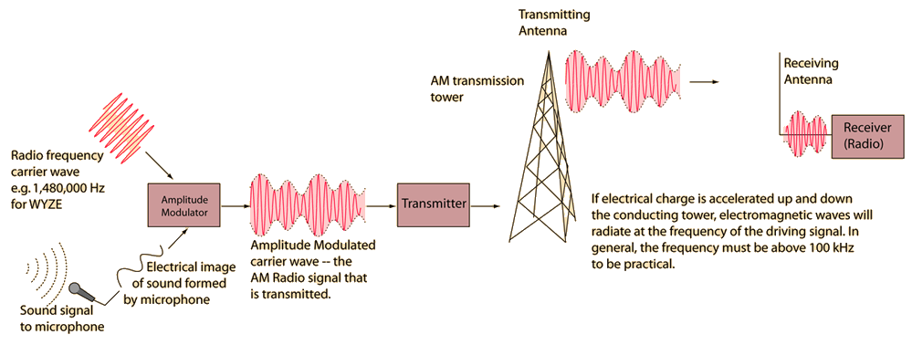
This is a sketch of some of the components involved in AM radio transmission. You may click on the illustration for more detail.

Electronics concepts
Diode varieties
| HyperPhysics*****Electricity and magnetism | R Nave |
AM TransmissionThis is a sketch of some of the components involved in AM radio transmission. You may click on the illustration for more detail.  |
Index Electronics concepts Diode varieties | ||
|
Go Back |
AM Radio Receiver

|
Index Electronics concepts Diode varieties | ||||
|
Go Back |
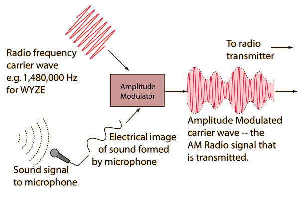
AM Modulation Stage for AM Radio In order to generate the radio frequency signal for AM radio transmission, the information contained in the original sound signal must be put in a form that can be sent to a great distance. When information from a voice is broadcast on an AM radio station, an electrical image of the sound is made by a microphone. A dynamic microphone is an example. That electrical signal or a signal from another recorded source is used to modulate the amplitude of the much higher frequency carrier wave. The electrical image of the sound information is used to vary the amplitude of the carrier wave by an amount porportional to the strength of the original sound signal. The modulated carrier wave is then amplified by the transmitter, which amounts to a power amplifier which can apply the modulated electrical wave to the conducting element in the transmitting broadcast antenna of the radio station. The AM band of the Electromagnetic spectrum is between 535 KHz and 1605 kHz and the carrier waves are separated by 10 kHz. |
Index Electronics concepts Diode varieties | ||
|
Go Back |
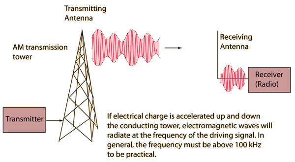
AM Transmission Stage The electrical signal from the AM modulation stage contains the information to be transmitted superimposed on the precisely controlled carrier frequency wave. Neither sound waves themselves nor electrical signals at audio frequencies can be transmitted over large distances. The AM band of frequencies is between 535 KHz and 1605 kHz, corresponding to wavelengths between approximately 200 and 600 meters. These long wavelengths dictate long conducting antennas, so it is customary to see metal towers or antennas on top of mountains or tall buildings. The radio transmitter is a power amplifier which provides enough power to generate radio frequency electric currents in the conducting broadcast antenna. Such antennae for AM radio are vertical, which leads to transmitted electromagnetic waves which are linearly polarized in the vertical direction. The electromagnetic waves, transmitted at the speed of light, are received by metallic antennae on the radio receivers. These antennae must also be oriented vertically for optimum reception. FM radio signals, by contrast, are transmitted with both horizontally and vertically polarized signals, so vertical antennae are not required. |
Index Electronics concepts Diode varieties | ||
|
Go Back |