Zener Regulator Design
One approach to Zener regulator design is to consider the desired load current and the amount of ripple present in the available unregulated supply.
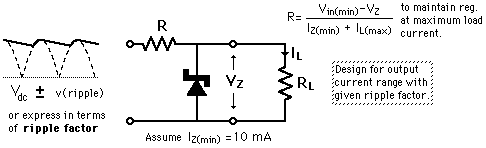
This design strategy is a practical, operational one: to design for a ripple-free output voltage up to a specified current maximum. Once done, you can choose load resistances which push the current up to this maximum and maintain regulation. However, it is easy to choose load resistances which push the current over the design maximum, and then the powers which this routine calculates will not be correct - they assume that the zener diode is operating at it's design voltage, and if you choose too small a load resistance, you drop the supply voltage at the zener below that voltage. The zener would then be acting like a voltage source, which of course it cannot do - it must have a supply voltage greater than the design voltage in order to regulate to that voltage.
Calculation note: You may substitute values for the zener voltage, the input voltage, the ripple voltage or ripple factor, and the load resistor. The other parameters will be calculated. Default values will be entered for unspecified parameters used in the calculation.
Caution about use of the ripple factor: the relationship between the ripple factor and the amplitude of the ripple factor uses some details about the nature of common filters, and the numerical value of the ripple factor will be accurate only for rectified 60 Hz inputs where the ripple is fairly small. See the development of the ripple expression.
.| Alternate Design Strategy |
Electronics concepts
Diode varieties
| HyperPhysics*****Electricity and magnetism | R Nave |