Sound Amplification Systems
Physics 4060: Acoustics Laboratory
The key issue in the study of sound amplification systems is the fact that the sound amplification is usually limited by the feedback condition and not by the power of the amplifier. A common experience is that of having a powerful amplifier and finding that you can only turn the gain up to 1 or 2 out of ten before the system "rings" or goes into the feedback condition. The point of this laboratory is to examine those things which may be done to the amplification system to increase the acoustic gain before feedback. This maximum feedback-free gain is called the "potential acoustic gain" (PAG) of the system.

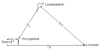
Figure 1: Simplified model of an amplification system
A good first step in understanding what can be changed to increase the gain before feedback is to develop a simplified model of an amplification system. The sketch in Figure 1 will be used to calculate the potential acoustic gain. This model makes two basic assumptions:
1. The sound drops off according to the inverse square law.
2. Speakers and microphones respond equally in all directions (omnidirectional).
Neither of these assumptions is realistic for any real sound system, but they provide a starting framework with which to pin down the significant variables which affect the sound system.


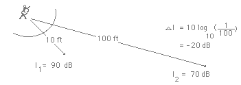
Figure 2: Illustrations of the Inverse Square Law
With the inverse square law, the sound level will drop six decibels with each doubling of the distance from the source. The relationship is
change in dB = 10 log10(I/I0) = 10 log10(r02/r2) = 10 log10(1/4) = -6 dB.
If we choose a set of distances for our simplified model which are related to each other by doublings, then we can use the 6 dB rule to examine the potential acoustic gain with minimal computation.
Assume Ds = 2 ft Source = 80 dB (forte ) at 2 ft
D1 = 32 ft at the microphone
D2 = D0 = 128 ft
Now with these values the sound intensity is 44 dB (music level ppp) at the listener when there is no amplification (D0 = 128 ft, drop 6 dB for each doubling from 6 ft until you reach 128 ft.)
The maximum electronic amplification you can use is determined by feedback considerations. Feedback will occur when the sound signal returning to the microphone from the loudspeaker is as strong as the original signal (in this case, 80 dB). The returning signal will be reamplified and sent back to the speaker and around the loop again. Under this condition you can walk up to the microphone and play one note and go home - the signal will "chase its tail" around the amplifecation system and produce sound the rest of the day. If the signal "feeding back" is stronger than the original signal, then it will continue to build up with each circuit until it reaches the maximum output of the amplifier, blows the speaker cone, or burns up the output stages of the amplifier. Practically speaking, there is usually one frequency of maximum gain which will start feedback first, so a system will usually "ring" or feedback at a single frequency.
If your hypothetical system is at the feedback point with 80 dB returned to the microphone by the loudspeaker, (a distance of 32 ft from the loudspeaker), then it is at maximum gain. By the 6 dB rule, the amplified sound at the listener's distance from the loudspeaker (128 ft) is at 68 dB. Therefore, the potential acoustic gain of this system is
P.A.G. = 68 dB - 44 dB = 24 dB.
Equivalently, the potential acoustic gain can be calculated by

or
P.A.G. = 20 (log10D1 + log10D0 - log10 Ds - log10 D2).
This last formal expression demonstrates how each distance affects the potential acoustic gain. The P.A.G. can be increased by:
1. Increasing D1, the microphone-to-loudspeaker distance, since you can use more amplification before feedback occurs. This no longer helps past the "critical distance" where reverberant sound equals direct sound since further increases in distance do not significantly reduce the feedback.
2. Increasing D0, the source-to-listener distance -- but this is not really meaningful since if you are further away the needed acoustic gain will also increase.
3. Decreasing D2, the loudspeaker-to-listener distance. Using multiple loudspeakers makes use of this principle, but digital delays should be used on distant speakers so that the sound from those speakers reaches the listener about the same time as the direct sound.
4. Decreasing Ds, the source-to-microphone distance. This is of limited usefulness, but allows you to operate the amplifier at a lower gain. Close-miking is a help if part of the signal leading to feedback is room noise or other extraneous signals.
Departing from the simplified model with its assumptions of inverse square law and omnidirectional microphones and loudspeakers, other things can be done to increase the P.A.G.
5. Use directional loudspeakers so that the feedback to the microphone is less than the sound projected to the listener.
6. Use directional microphones so that the microphone discriminates against the sound feeding back from the loudspeaker.
7. Use a minimum number of microphones - nominally, doubling the number of open microphones decreases the P.A.G. by 3 dB.
8. Use filtering or equalization to level out the frequency response curve of the amplification system in that particular room or auditorium so that one frequency doesn't reach the feedback point while most of the other frequencies of sound are at relatively low gain.
Equalization is one of the major advances in sound amplification systems during the last few years. It not only increases the P.A.G., but also improves the overall sound quality. It has been made possible by reasonably priced spectrum analyzers which sweep quickly through the audio spectrum and display the output in essentially "real time" - hence their usual name "real time analyzers". With white or pink noise input to the sound system, the signal picked up by a standard microphone is fed to the analyzer. Then on the input side, filters or equalizers are used to adjust the system frequency response for the condition "white noise in - white noise out" or "pink noise in - pink noise out". This equalization takes into account the effects of the room or auditorium, so the phrase "equalizing to the room" is often used. This process has been a great boon to traveling musical groups.
PROCEDURE
The experiment will involve measuring the potential acoustic gain (P.A.G) for a sound amplification system. This involves measuring the sound level without amplification and then increasing the amplification to the threshold of feedback and remeasuring the sound level. The difference is the P.A.G. The dBA response of the sound level meter will be used for all measurements to discriminate against low frequency background noise.
Choose a standard location for your microphone and leave it fixed in place. Measure the background dBA level. Choose a source position - for example 25 cm from the microphone. Record the distance from microphone to the sound level meter. Produce pink noise in the room at a level significantly above background - e.g., 10 dBA above background without any amplification.
I. Place the output speaker one meter away from the microphone and pointing away from the microphone and measure the P.A.G.
II. Point the loudspeaker toward the microphone and remeasure the P.A.G.
III. Increase the distance from the microphone to the speakers at 1 meter intervals with loudspeakers pointed away from the microphone, measuring the P.A.G at each position.
IV. With speakers at two meters, measure the P.A.G if the distance from source to microphone is cut in half.
V. Using the 2 meter speaker distance, produce pink noise through the system at a level at least 10 dBA above background. Assess the equalization with the Goldline real time analyzer (equalized sound should line up the LEDs in a horizontal row). Use the graphic equalizer, bass and treble controls, etc. to get as near to equalization as you can and remeasure the P.A.G.