Voltage Divider
The two resistor voltage divider is used often to supply a voltage different from that of an available battery or power supply. In application the output voltage depends upon the resistance of the load it drives.

where
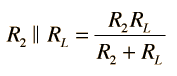
is the parallel resistance of R2 and the load resistor RL.
The voltage divider is a very important basic circuit, and exploring the calculation above with various values can give you insight into a large number of practical circuit applications. One practical consideration is that a larger value of R2 compared to R1 will give you a larger output voltage. But if your load resistance RL is smaller than R2, you will diminish the output voltage and require a larger current and total power from the power supply. You would find upon exploration that for a given set of values for the voltage divider (R1 and R2), you will get more power to the load if you decrease the load resistor RL but is comes at the expense of higher current and power from the power supply.
Note: To avoid dealing with so many short circuits, divider resistors with value zero will default to 1 when the voltage is changed and the load will default to 1000. They can be changed back to a zero value if you wish to explore the effects of short circuits. Ohms are indicated as the resistance unit, but kilohms are more common and of course the calculation is the same.
| DC circuit examples | AC voltage divider |
DC Circuits
| HyperPhysics***** Electricity and Magnetism | R Nave |