Experiment #1: D.C. Circuits
Reference: Simpson Ch 1, Appendices A & CObjective: To become familiar with Ohm's law, Kirchoff's laws and their use in analyzing basic D.C. Circuits containing only resistors.
Procedure: Digital multimeters will be used for the voltage and current measurements. Refer to the description of the multimeter in the lab manual for further details. The voltage will be obtained from the Pasco power supply (refer to the instructions). Note that part IIIB can be done outside of lab.
I. Series Circuits:
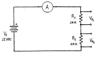
A. Wire the circuit shown in Figure 1.

- Measure and record the values for the current, the voltage across R1 (VR1) , the voltage across R2 (VR2), and the supply voltage. Remove, measure and record the values of your resistors.
- In order to have the meters read in the "forward" direction the
connections to the + and - meter terminals must be one of the
two possibilities.
- Sketch your circuit showing its working connections
- Justify the connections in terms of Ohm's law and the direction of current flow.
- Calculate the current based on the resistance values (see the text for a color code chart) and compare it with the result from part 1. If there is a difference, is it reasonable?
II. Parallel Circuits
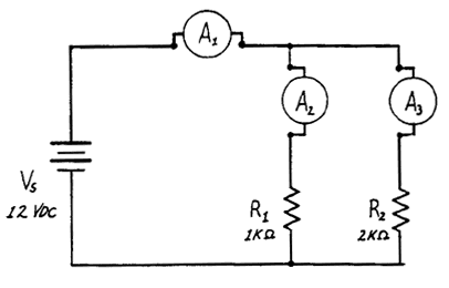
A. Wire the circuit shown in Figure 2.

- Measure and record the voltages across R1 and R2 and the power supply. Record your resistor values. Show on a sketch the connections of the + and - meter leads.
- Insert the milliammeter into the circuit in each of the locations (A1), (A2), and (A3) in turn. Record each reading, and show on a sketch the orientation of the + and - connections.
- Compare the value of (I1) with those of (I2) and (I3). Is the comparison reasonable in terms of circuit theory?
III. More Complicated Circuit
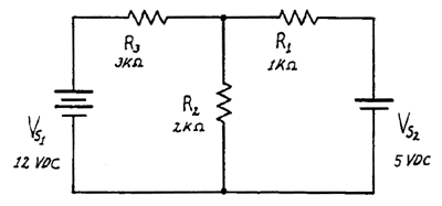
A.Set up the circuit shown in Figure 3.

- Double-check your wiring to be sure it is as the schematic shows.
- Measure and record the voltages across each resistor. Make a sketch showing the polarity of the voltages as indicated by the polarity of the voltages as indicated by the voltmeter connections. From the voltage across each R, calculate the current through the resistors.
| Sample data and setup |