RLC Series Circuit

The RLC series circuit is a very important example of a resonant circuit. It has a minimum of impedance Z=R at the resonant frequency, and the phase angle is equal to zero at resonance.

Calculation
Index

Capacitance concepts

Inductance concepts

AC circuit concepts
 
HyperPhysics***** Electricity and Magnetism R Nave
Go Back


RLC Series Impedance

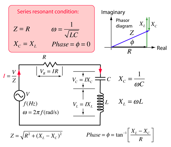
The frequency dependent impedance of an RLC series circuit
For C = x10^ F = μF = pF
and L = x10^ H = mH = microHenries
at angular frequency ω = x10^ rad/s,
frequency = x10^ Hz = kHz = MHz
and resistance R = x10^ ohms = kohms = Megohms,

the impedance is

Z = x10^ ohms = kohms = Megohms

at phase φ = degrees.
The resonant condition is
Angular frequency ω = x10^ rad/s,
Frequency f = x10^ Hz
Z = R = x10^ ohms
Phase φ = 0

For an applied rms voltage V = volts,

the rms current will be I = x 10^ amperes.

The component voltages can be obtained by multiplying the current times the component impedances.

Capacitor: VC = IXC = volts.
Inductance: VL = IXL = volts.
Resistor: VR = IR = volts.

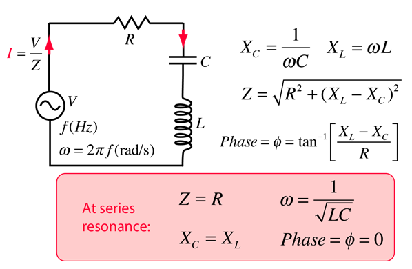
When exploring the values for real circuits, it is easy to find examples where both VL and VC are larger than the resultant voltage V. This can occur because these voltages VL and VC act 180° out of phase with each other. You can visualize this from the phasor diagram by seeing that both VL and VC can be large and that they exactly cancel each other at resonance.

Default values will be entered for unspecified parameters, but all component values can be changed. Click outside the box after entering data to initiate the calculation.
AC behavior of RLC series circuit
Index

Capacitance concepts

Inductance concepts

AC circuit concepts


Resonant Frequency Calculator
 
HyperPhysics***** Electricity and Magnetism R Nave
Go Back