Moving Coil Meters

The design of a voltmeter, ammeter or ohmmeter begins with a current-sensitive element. Though most modern meters have solid state digital readouts, the physics is more readily demonstrated with a moving coil current detector called a galvanometer. Since the modifications of the current sensor are compact, it is practical to have all three functions in a single instrument with multiple ranges of sensitivity. Schematically, a single range "multimeter" might be designed as illustrated.

Voltmeter designAmmeter designOhmmeter design
Voltmeter/Ammeter measurements of resistance
Index

DC Circuits
 
HyperPhysics***** Electricity and Magnetism R Nave
Go Back


Voltmeter

A voltmeter measures the change in voltage between two points in an electric circuit and therefore must be connected in parallel with the portion of the circuit on which the measurement is made. By contrast, an ammeter must be connected in series. In analogy with a water circuit, a voltmeter is like a meter designed to measure pressure difference. It is necessary for the voltmeter to have a very high resistance so that it does not have an appreciable affect on the current or voltage associated with the measured circuit. Modern solid-state meters have digital readouts, but the principles of operation can be better appreciated by examining the older moving coil meters based on galvanometer sensors.
Details of voltmeter design
Index

DC Circuits
 
HyperPhysics***** Electricity and Magnetism R Nave
Go Back


Ammeter

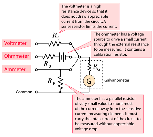
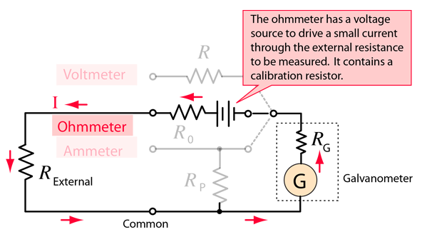
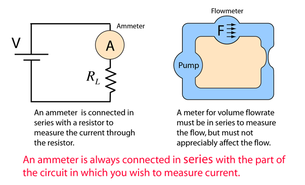
An ammeter is an instrument for measuring the electric current in amperes in a branch of an electric circuit. It must be placed in series with the measured branch, and must have very low resistance to avoid significant alteration of the current it is to measure. By contrast, an voltmeter must be connected in parallel. The analogy with an in-line flowmeter in a water circuit can help visualize why an ammeter must have a low resistance, and why connecting an ammeter in parallel can damage the meter. Modern solid-state meters have digital readouts, but the principles of operation can be better appreciated by examining the older moving coil meters based on galvanometer sensors.

Details about ammeter design
Index

DC Circuits
 
HyperPhysics***** Electricity and Magnetism R Nave
Go Back


Ohmmeter

The standard way to measure resistance in ohms is to supply a constant voltage to the resistance and measure the current through it. That current is of course inversely proportional to the resistance according to Ohm's law, so that you have a non-linear scale. The current registered by the current sensing element is proportional to 1/R, so that a large current implies a small resistance. Modern solid-state meters have digital readouts, but the principles of operation can be better appreciated by examining the older moving coil meters based on galvanometer sensors.

Voltmeter/Ammeter measurements of resistance
Index

DC Circuits
 
HyperPhysics***** Electricity and Magnetism R Nave
Go Back


Voltmeter/Ammeter Measurements

The value of electrical resistance associated with a circuit element or appliance can be determined by measuring the voltage across it with a voltmeter and the current through it with an ammeter and then dividing the measured voltage by the current. This is an application of Ohm's law, but this method works even for non-ohmic resistances where the resistance might depend upon the current. At least in those cases it gives you the effective resistance in ohms under that specific combination of voltage and current.

For V = volts and I = A, then RL =Ω
For V = volts and I = mA, then RL =
Index

DC Circuits
 
HyperPhysics***** Electricity and Magnetism R Nave
Go Back