Fraunhofer Single Slit
This is an attempt to more clearly visualize the nature of single slit diffraction. The phenomenon of diffraction involves the spreading out of waves past openings which are on the order of the wavelength of the wave. The spreading of the waves into the area of the geometrical shadow can be modeled by considering small elements of the wavefront in the slit and treating them like point sources.
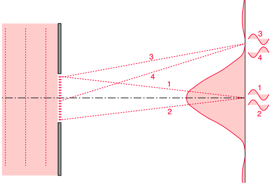
If light from symmetric elements near each edge of the slit travels to the centerline of the slit, as indicated by rays 1 and 2 above, their light arrives in phase and experiences constructive interference. Light from other element pairs symmetric to the centerline also arrive in phase. Although there is a progressive change in phase as you choose element pairs closer to the centerline, this center position is nevertheless the most favorable location for constructive interference of light from the entire slit and has the highest light intensity if the Fraunhofer diffraction expression is reasonably applicable. If the conditions D >> a and D>> a2/λ are not met for this combination of slit width and screen distance, the Fresnel diffraction result may not have maximum intensity on the centerline.
The first minimum in intensity for the light through a single slit can be visualized in terms of rays 3 and 4. An element at one edge of the slit and one just past the centerline are chosen, and the condition for minimum light intensity is that light from these two elements arrive 180° out of phase, or a half wavelength different in pathlength. If those two elements suffer destructive interference, then choosing additional pairs of identical spacing which progress downward across the slit will give destructive interference for all those pairs and therefore an overall minimum in light intensity.
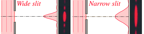
One of the characteristics of single slit diffraction is that a narrower slit will give a wider diffraction pattern as illustrated below, which seems somewhat counter-intuitive. One way to visualize it is to consider that rays 3 and 4 must reach one half wavelength difference in light pathlength, and if the slit is narrower, it will take a greater angle of the rays to achieve that difference.
The diffraction patterns were taken with a helium-neon laser and a narrow single slit. The slit widths used were on the order of 100 micrometers, so their widths were 100 times the laser wavelength or more. A slit width equal to the wavelength of the laser light would spread the first minimum out to 90° so that no minima would be observed. The relationships between slit width and the minima and maxima of diffraction can be explored in the single slit calculation. |
These Fraunhofer single slit diffraction images were taken with laser sources, which easily give you the conditions under which Fraunhofer diffraction applies, i.e., the laser beam produces an essentially infinite effective object distance. The Fraunhofer diffraction conditions can also be produced by using two lenses, with a source slit placed at the focal length of the first lens, and the viewing screen placed past the second lens at its focal length. This arrangement is shown below.

The lens arrangement forces the beam to be parallel to the axis at the position of the diffracting slit.
|
|
|
Diffraction concepts
Fraunhofer diffraction
Jenkins & White, Ch 15
| HyperPhysics***** Light and Vision | R Nave |