Clocked Set-Reset Flip-flop
Example Output

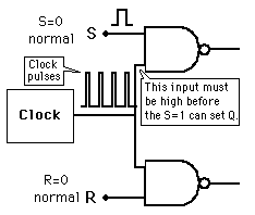
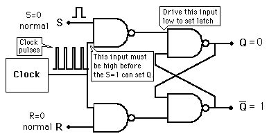
When the signal line S goes high, the other line to the NAND gate from the pulse steering circuit must also be high for it to generate a low output. Likewise, a clock pulse must have the reset NAND gate high to receive a high RESET pulse. Therefore all transitions are synchronized to the clock.

Set-reset Flip-flopNAND-gate Latch
Index

Electronics concepts

Digital circuits
 
HyperPhysics*****Electricity and magnetismR Nave
Go Back


Pulse-Steering Circuit

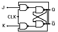
In the case of the J-K flip-flop, the pulse steering circuit is tied to the output lines past the NAND gate latch. This gives it the toggle action when J and K are both high.

In order to add clock synchronization to a flip-flop, a ciruit is used to apply the clock pulses to the flip-flop. To convert a NAND gate latch to a clocked S/R flip-flop, two NAND gates may be used as above left to enable an input pulse on either the S or R lines to trigger a transition.

NAND-Gate Latch
Index

Electronics concepts

Digital circuits
 
HyperPhysics*****Electricity and magnetismR Nave
Go Back


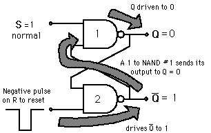
Resetting the NAND Latch

Return to reset state.

The time sequence at right shows the conditions under which the set and reset inputs cause a state change, and when they don't.

NAND-Gate Latch
Index

Electronics concepts

Digital circuits
 
HyperPhysics*****Electricity and magnetismR Nave
Go Back