Circuit Equations:Transformer

The application of the voltage law to both primary and secondary circuits of a transformer gives:

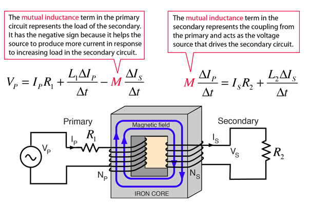
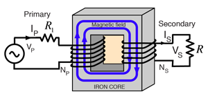
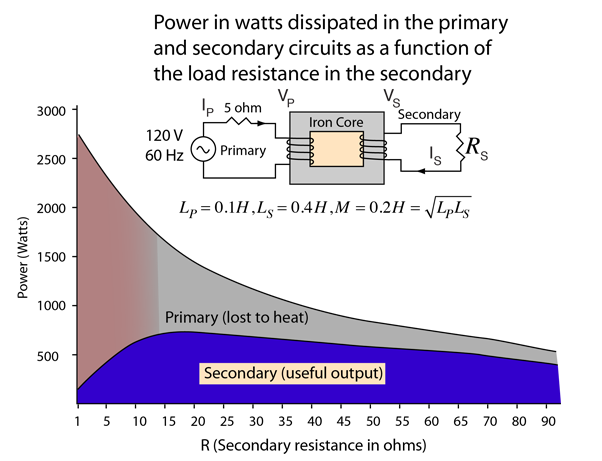
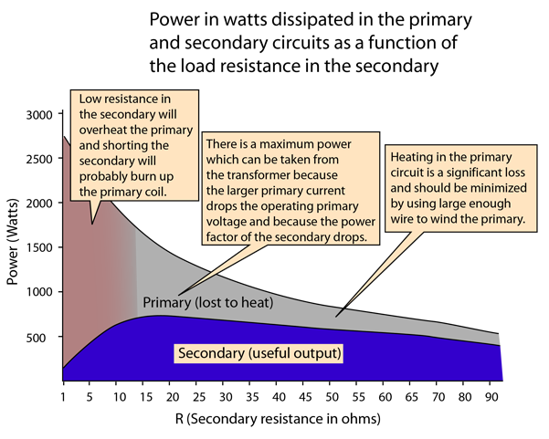
The transformer is the most common application of the concept of mutual inductance. In the transformer, the effect of the mutual inductance is to cause the primary ciruit to take more power from the electrical supply in response to an increased load on the secondary. For example, if the load resistance in the secondary is reduced, then the power required will increase, forcing the primary side of the transformer to draw more current to supply the additional need.

Circuit Equation SolutionsCalculation
Index

Transformer concepts

Faraday's law concepts

Inductance concepts
 
HyperPhysics***** Electricity and Magnetism R Nave
Go Back


Circuit Equations: Transformer

The secondary circuit equation is that of an RL circuit driven by a voltage source:

The primary circuit current is given by:

Show

Note that the effective impedance of the primary circuit contains not only the coupling of the mutual impedance, but contains terms dependent upon the secondary load resistor R. When R is smaller (greater load) , ZP becomes smaller and more resistive, taking more power from the primary source.

For ideal coupling, the mutual inductance becomes

Development of EquationsNumerical ExamplePower Calculation
Index

Transformer concepts

Inductance concepts

AC Circuits
 
HyperPhysics***** Electricity and Magnetism R Nave
Go Back


RS
Ohms
VP
Volts
VS
Volts
IP
Amps
IS
Amps
PP
Watts
PS
Watts
Open
119
238
3.2
0
50
0
100
99
198
4.8
2.0
114
395
20
60
120
12.1
6.0
729
717
5
24
48
19.2
9.6
1844
460
1
5.7
11.4
22.9
11.4
2612
131


Development of EquationsPlot of DataCalculation
Index

Transformer concepts

Inductance concepts

AC Circuits
 
HyperPhysics***** Electricity and Magnetism R Nave
Go Back


Data table and explanationAdd annotation to the load curvesCalculation
Index

Transformer concepts

Inductance concepts

AC Circuits
 
HyperPhysics***** Electricity and Magnetism R Nave
Go Back


There is a practical midrange of load resistances for the operation of a transformer. In the example above, you can see that maximum output power is obtained with a load resistance between 15 and 20 ohms. When too heavy a load is drawn from the secondary, the primary coil heats up and the amount of audible "hum" that you hear from the transformer increases. My brother, Edgar Nave, worked in commercial electrical construction and wired many large transformers. He reports incidents when the secondary of a transformer was shorted, and says that the transformer would "squawl" like a wounded beast before it burned up the primary coil.

Data table and explanationPlot and circuit diagramCalculation
Index

Transformer concepts

Inductance concepts

AC Circuits
 
HyperPhysics***** Electricity and Magnetism R Nave
Go Back


Circuit Equations:Transformer

The application of the voltage law to both primary and secondary circuits of a transformer gives:

Obtaining the circuit equations requires the simultaneous solution of the primary and secondary circuit equations. That solution is facilitated by using the complex impedance method, presuming a sinusoidal supply voltage with angular frequency ω. Standard AC practice uses rms currents and voltages, and in the complex impedance approach the derivative of current dI/dt = jωI. The primary and secondary loop equations then take the form:

From the secondary circuit equation we can find an expression for the secondary current IS.

This can be substituted into the primary loop equation:

The last term can be rationalized by multiplying numerator and denominator by

giving

This allows us to separate the real and imaginary parts and place the expression in the form of a standard complex number.

This can be written in the form of a standard AC circuit impedance Z:

where

Transformer Circuit EquationsCircuit Equation SolutionsCalculation
Index

Transformer concepts

Faraday's law concepts

Inductance concepts
 
HyperPhysics***** Electricity and Magnetism R Nave
Go Back